


SARA-N310 module
Multi-band NB-IoT (LTE Cat NB2) module
Tech
|
28 Apr 2022
Monitoring of a remote location is a typical IoT application, but target use cases are different.

Monitoring of a remote location is a typical IoT application, but target use cases are different. Very often, observed parameters are not expected to change quickly and are not critical per se, but business owners are asking for regular updates, e.g., once a day. Let’s take the example of a “forest sensor”, an IoT solution for monitoring health condition of trees. For this purpose, a battery-powered sensor device is mounted to a tree and grabs some vital and environmental parameters - containing valuable information to forest owners which are interested to optimize growth, yield, etc.
But in open-air environments like a forest there will be no power outlet available, and no LAN can be used. This is why, for this kind of use case, an IoT sensor should be powered by battery, and a cellular network should be used in order to ensure reliable operation. In addition, the IoT device should be prepared for zero-touch operation during its complete product lifecycle, i.e. it should be 100% maintenance-free and should not need any battery replacement or re-charge for many years. This means that our forest sensor IoT device should be designed for maximum power efficiency.
This is a typical “push” application where the IoT device is inactive for most of the time, just “waking up” occasionally as soon as it has been triggered by a fixed schedule or an external event. There are many IoT use cases like this, e.g., a meter device providing a container fill level or a tracking device providing the geo position of an asset. As a matter of fact, NB-IoT cellular network particularly has been specified to meet this kind of requirements, especially if stationary IoT devices are used for infrequent transmission of small payload data packages.
In order to support reduction of IoT device power consumption as much as possible, NB-IoT network technology offers a nice feature called power saving mode (short: PSM) which allows an NB-IoT device to switch off most parts of the network interface including its transceiver RF section for an agreed period of inactivity.
The duration of this interval is determined by network timer T3412 (aka “TAU Timer”) which is primarily used by the NB-IoT device to perform a periodic Tracking Area Update (TAU). This is a standard LTE feature to notify the availability of a user device to the connected network. In fact, once the device has been connected successfully to the network, it remains registered during PSM intervals, but transmission activity may wait until T3412 timer has expired. By nature, longer PSM periods will result in less power consumption. Depending on the IoT use case, it is now up to the developer to determine the ideal time period for their device to remain in PSM mode.
According to 3GPP specification, T3412 can be programmed for PSM intervals of up to 413 days (!). But unfortunately, implementations are different, and it will depend on the owner of the network infrastructure which T3412 intervals are allowed... For our IoT device concept, the specialized NB-IoT network interface module u-blox SARA-N310 has been selected. Users of this module will use AT command +CPSMS (Power Saving Mode Setting) to request configuration of a specific T3412 value, then check whether the request has been granted to the IoT device by means of the AT+CEREG=4 command (EPS network registration status). For AT command details see Ref. 1.
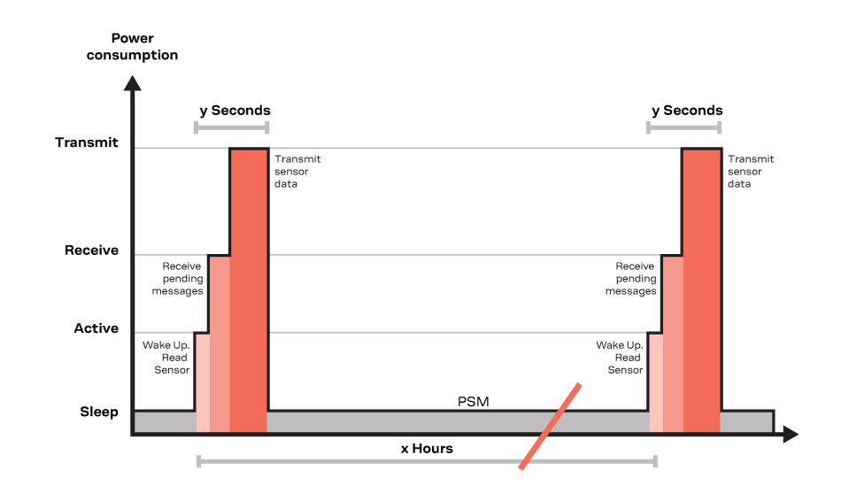
Figure 1: Periodic device activity (simplified)
During agreed PSM periods all download traffic to the registered but unreachable IoT device will be buffered by the network. Our design concept for a battery-powered “push” device is based on the idea that all local IoT activities are handled during a single periodic time slot (see Figure 1), i.e., read sensor, receive pending messages (e.g., an operator remote control command), transmit IoT payload data. Most of the time (approx. 99,99%), the device will remain in deep sleep mode and consumes few µA during this time. After T3412 has expired, the SARA-N3 module will retrieve pending messages from the network, if any. During reception events the module will consume 46 mA, during uplink transmission it will ideally draw 220 mA at 23dBm output power. Over time, frequency and duration of these short power consumption peaks will have a significant impact on battery lifetime. It is no surprise that doubling the frequency of activity periods (e.g., from once-a-day to twice-a-day) will decrease battery lifetime by half.
But on top of this, there are many other additional aspects which will contribute to the overall power consumption of the device (see also Ref. 3, chapter 20 “Design for reduced power consumption”). For example, positioning and impedance matching of the device antenna are critical design aspects which are significantly impacting RF performance. Antenna matching is required to maximize output power at a specific NB-IoT carrier frequency. In general, device location has an impact on power consumption and distance to connected cell tower should be as short as possible in order to maximize signal efficiency and quality. This is a critical point because operation of battery-powered devices at coverage extension (CE) level 2 should be avoided. This NB-IoT feature is helpful to provide coverage in difficult-to-reach areas, but works with repetitions and extra error correction codes which are dramatically increasing payload data overhead and transmission times. So, from a deployment point of view, it is beneficial to work with an MVNO (“virtual” network operator) allowing you to select from a choice of networks to connect to, instead of just one. See Ref. 4 for further explanation.
SARA-N3 offers several options to support low power device design based leveraging NB-IoT PSM feature (see Ref. 2). Requesting the NB-IoT network to enter PSM state can be initiated by the IoT device via AT command which allows the device to enter deep sleep for the agreed PSM interval. In deep sleep mode, the UART interface is not functional and there are only two ways to return the module to active state: after expiration of the internal periodic TAU timer or by an external wake-up event. External wake-up events are indicated by toggling the PWR_ON pin of the SARA-N3 module. This method can be used for a predefined local event, e.g., an exceeding threshold (e.g., saying “it is too hot”) or if presence of an object has been detected. This is another typical “push” IoT application which can be addressed by SARA-N3 respectively in cooperation with an NB-IoT network. But for our “forest sensor” example, we use the mentioned internal periodic TAU timer for wake up.
During agreed PSM periods, all device components are configured to work in their individual idle modes with extremely low power consumption. In order to achieve maximum battery lifetime oft the IoT device, proper orchestration of power management features of all three main components is required: u-blox SARA-N3 network module, host MCU and sensor (see block diagram Figure 2). Master role is alternating between two of them: IoT application program is executed by the host MCU, but wake-up management is handled by the SARA-N3 cellular module in cooperation with the NB-IoT network. This is done via V_INT output pin which is used internally as a power supply for digital interfaces, but also can be used as an external indicator that SARA-N3 currently is in deep sleep mode.
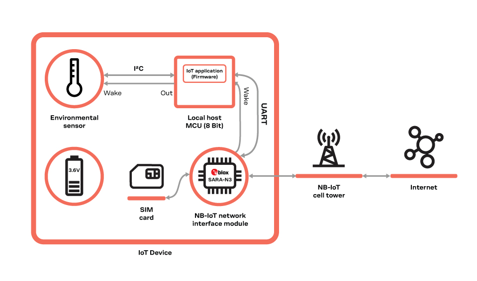
Figure 2: Block diagram
As such, whenever SARA-N3 has returned from deep sleep, its V_INT signal wakes up the host MCU and the embedded IoT application program (firmware) to take over control of the IoT device – according to use case requirements. For the IoT program, reconnection to the registered network and request for pending downlink messages will be the first things to do. Waking up the sensor chip and kicking off a measurement cycle also needs to be done within each single activity period (recall Figure 1). When finished, the MCU will pass IoT payload data to the SARA-N3 module, request for data conversion into selected protocol format (e.g., UDP or MQTT) and for data transmission. Finally, the MCU will ask SARA-N3 to initiate the next PSM period, and the IoT device re-enters specified infinite loop of activity and PSM cycles.
In the end, power consumption of each component during all active and idle periods will aggregate to the total power consumption of the IoT device. In our case, an 8-bit MCU and a sensor with low-power idle modes consuming less than 1 µA have been selected. For our calculation, we assume that we will have an activity slot every 12 hours (i.e., IoT data will be reported twice a day) which take 5 seconds each. During these active periods, device power consumption will be dominated by the RF power required to re-connect and transmit IoT data package to the network. For our use case, selected components and configured parameters for short activity periods and long PSM periods are leading to a total power consumption of (223+61) mAh = 284 mAh per year (refer to Ref. 4 for more detailed explanation). With this approach, a fixed AA-sized 3000mAh Lithium battery will provide an amazing zero-touch product lifetime of 10,5 years – which is a good value proposition for a remote monitoring IoT solution which can be used everywhere.
References:
1. u-blox SARA-N3 AT Commands Manual
2. u-blox SARA-N3 AT System Integration Manual
3. u-blox SARA-N3 AT Application Development Guide Manual
4. Kersten Heins “NB-IoT Use Cases and Devices”. Springer. ISBN 978-3-030-84973-3
Kersten Heins
IoT Technical Marketing